Embedded Series Product Guide
Artificial Intelligence Radio Transceiver (AIR-T)
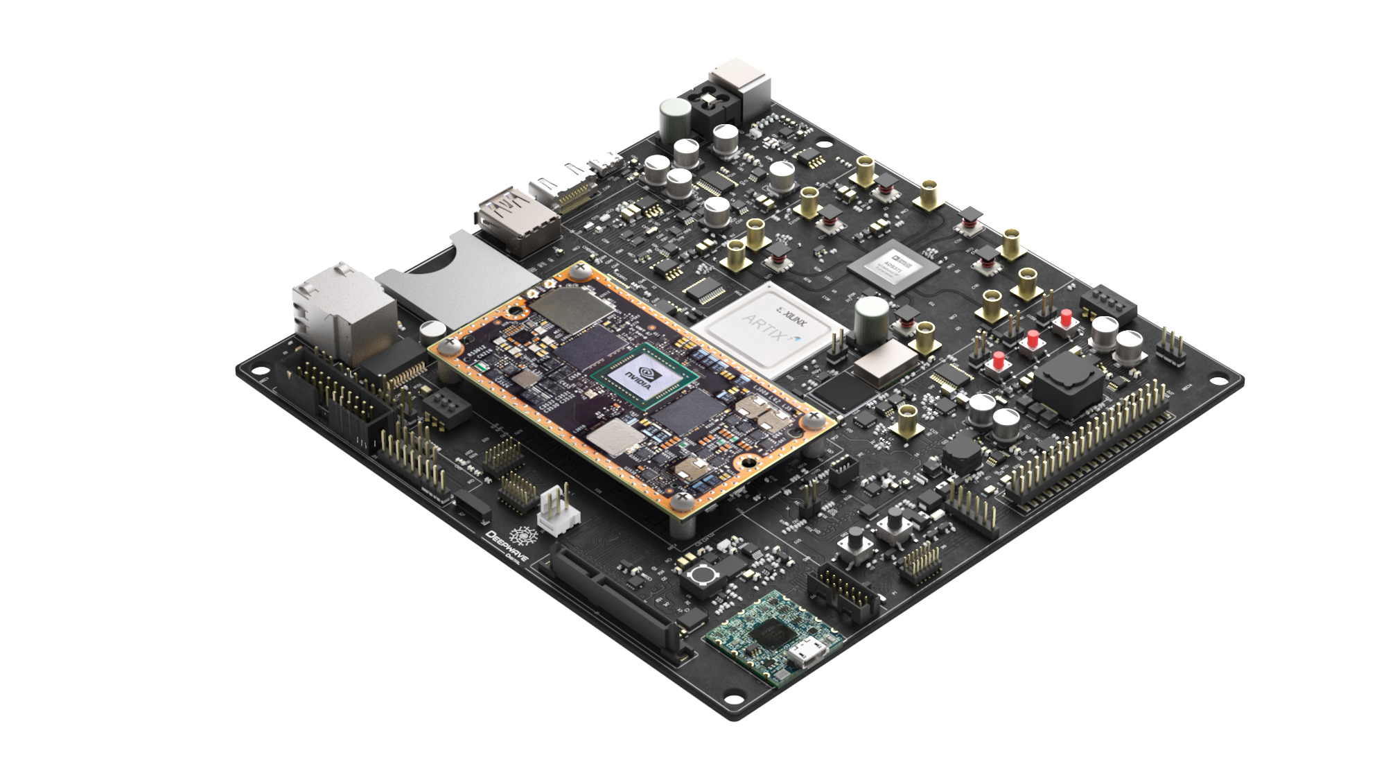
The Artificial Intelligence Radio Transceiver (AIR-T) is a high-performance software-defined radio (SDR) seamlessly integrated with state-of-the-art processing and deep learning inference hardware. The incorporation of an embedded graphics processing unit (GPU) enables real-time wideband digital signal processing (DSP) algorithms to be executed in software, without requiring specialized field programmable gate array (FPGA) firmware development. The GPU is the most utilized processor for machine learning, therefore the AIR-T significantly reduces the barrier for engineers to create autonomous signal identification, interference mitigation, and many other machine learning applications. By granting the deep learning algorithm full control over the transceiver system, the AIR-T allows for fully autonomous software defined and cognitive radio.
Out of the box, the AIR-T is a fully functioning SDR that includes numerous examples and open source APIs. The system includes AirStack, the AIR-T’s complete software package. AirStack consists of the Ubuntu operating system, drivers, FPGA firmware, and everything required for AIR-T operation.
Manufacturer Part Numbers
| AIR-T Model | GPU | FPGA | Part Number (Board Only) | Part Number (with Enclosure) |
|---|---|---|---|---|
| AIR7101 | NVIDIA Jetson TX2 | Xilinx Artix7 75T | AIR7101-A | AIR7101-B |
| AIR7201 | NVIDIA Jetson TX2 | Xilinx Artix7 200T | AIR7201-A | AIR7201-B |
Document Overview
This document lists the specifications for the Artificial Intelligence Radio Transceiver (AIR-T). Specifications are subject to change without notice. For the most recent device specifications, refer to http://docs.deepwavedigital.com.
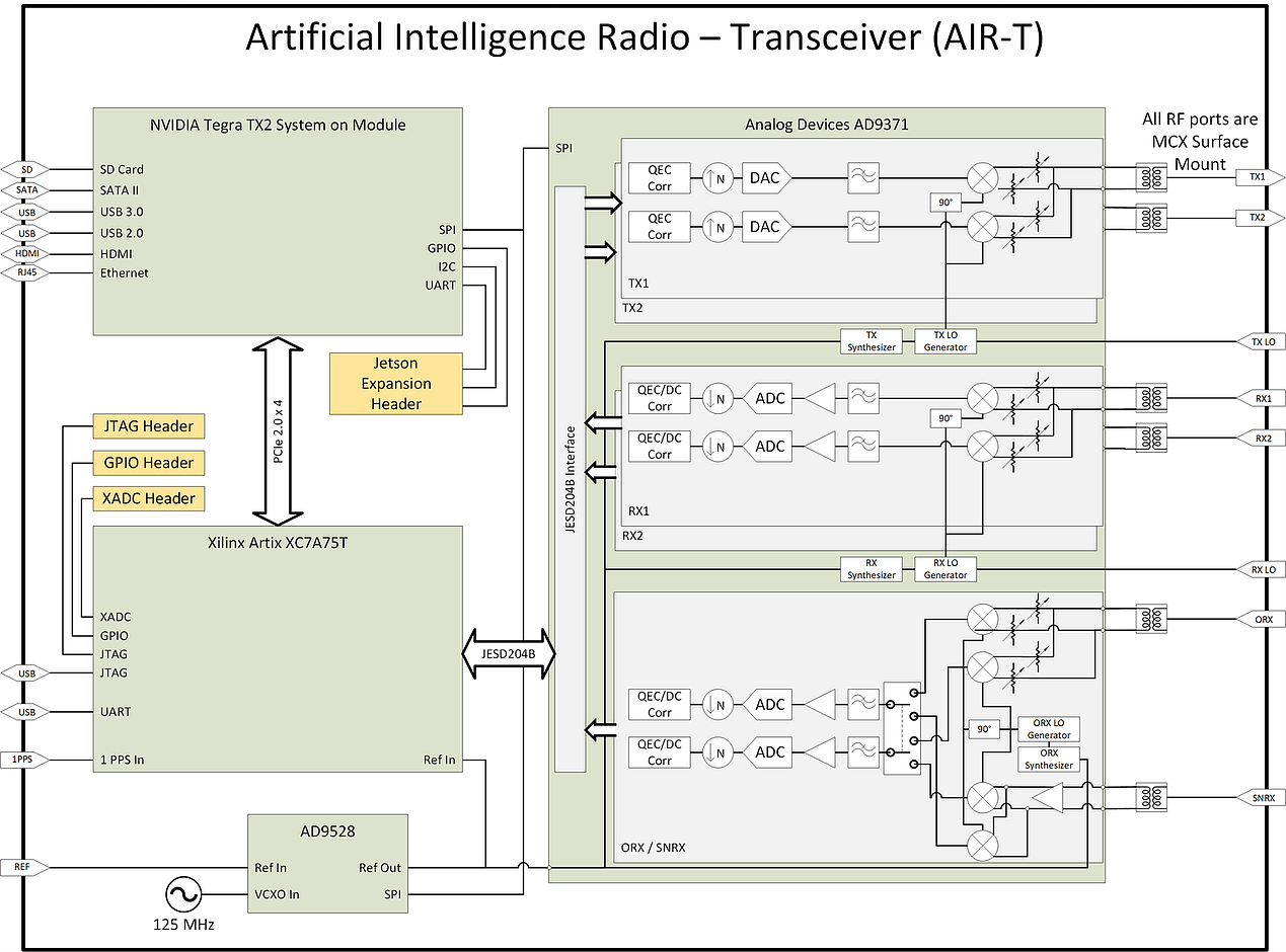
AIR-T Functional Diagram
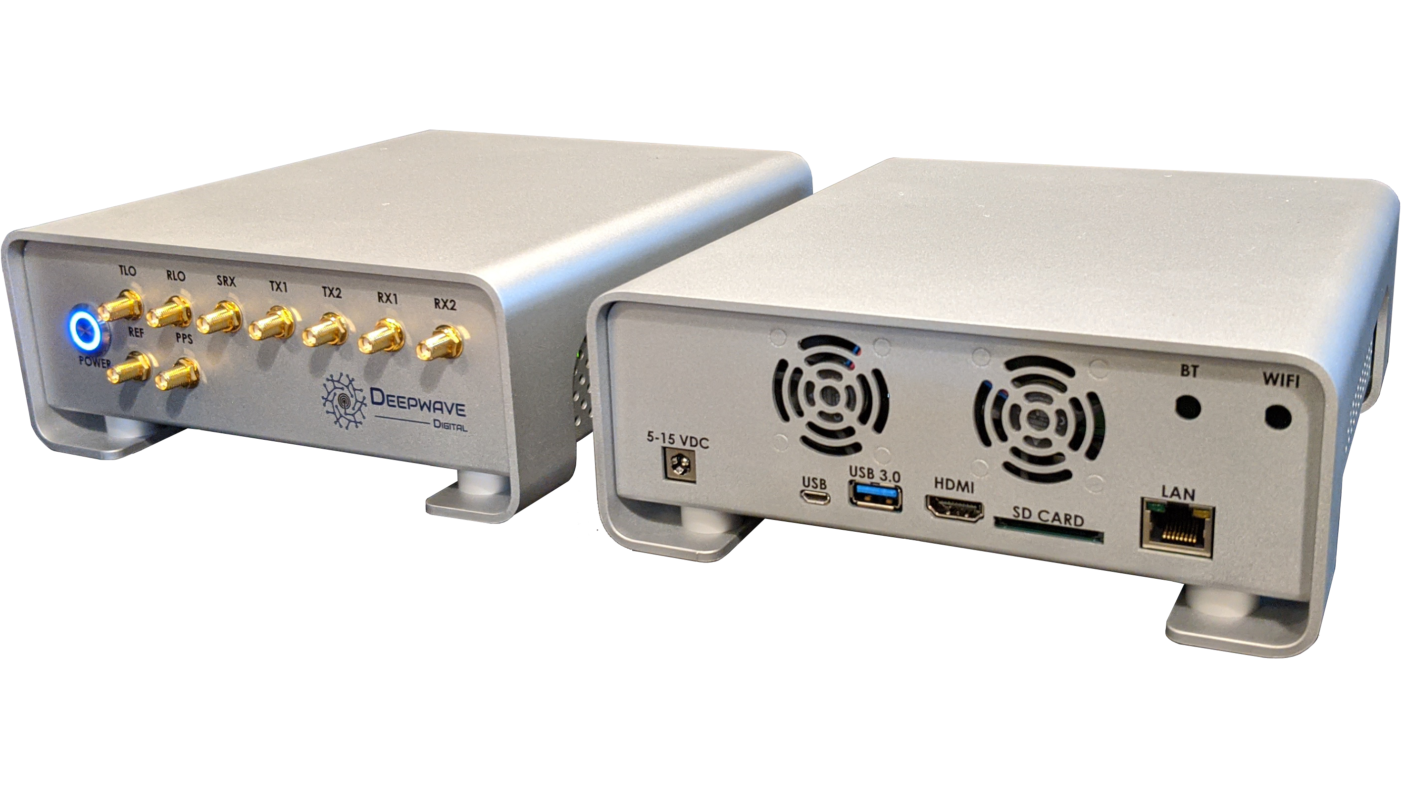
AIR-T Enclosure
The AIR-T may be purchased with or without an enclosure. This documentation applies to both configurations.
Mechanical Drawing
We provide a pdf file with the mechanical dimensions of the AIR-T enclosure below.

Processors
The AIR-T enables software defined radio for any signal processing application by utilizing three classes of tightly coupled processors: * FPGA for strict real-time operations * GPU for highly parallel processing and machine learning * CPU for control, I/O, DSP, and software applications
General Purpose Processors
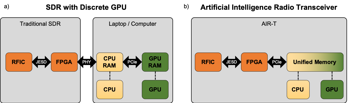
The AIR-T uses the NVIDIA Jetson TX2 System On Module (SOM) as its General Purpose Processor (GPP). The Jetson TX2 SOM contains two ARM processors (6 cores total), an NVIDIA Pascal GPU (256 cores), and 8 GBytes of memory. The CPUs and GPU all share a common pool of memory, which (along with a unified memory architecture) allows for a zero-copy capability. As illustrated in the figure below, zero-copy eliminates the host-to-device (or device-to-host) memory transfer that is required by SDRs with discrete GPUs, such as an SDR connected to an external laptop or computer. Because of this, an SDR with a discrete GPU will have increased latency that is prohibitive for many applications. By utilizing this zero-copy architecture to remove extra data transfers, the AIR-T enables a wide range of low-latency SDR applications.
For additional details on the NVIDIA Jetson TX2 please see the module datasheet URL below. Some of the information from that datasheet is produced below.
http://developer.nvidia.com/embedded/dlc/jetson-tx2-series-modules-data-sheet
| Table 1 | |
|---|---|
| Manufacturer | NVIDIA Corporation |
| Model | NVIDIA Jetson TX2 (GPU / CPU) |
| Packaging | System on Module (SOM) |
| GPU Type | NVIDIA Pascal GPU architecture with 256 NVIDIA CUDA cores |
| CPU Type | ARMv8 (64-bit) heterogeneous multi-processing CPU architecture with two CPU clusters (6 processor cores) connected by a coherent interconnect fabric. ARM Cortex -A57 MPCore (Quad-Core) Processor:
|
| Unified Memory (GPU/CPU shared) |
|
| Storage Capacity | 32GB eMMC 5.1 Flash Storage |
Reconfigurable FPGA
The FPGA on the AIR-T comes pre-loaded with the AirStack firmware to support transmit and receive functionality. Customers may choose to load custom firmware if needed by their application. Details regarding the FPGA on the AIR-T are shown below.
| Table 2 | AIR7101 | AIR7201 |
|---|---|---|
| Manufacturer | Xilinx | Xilinx |
| Family | Artix-7 | Artix-7 |
| Model | XC7A75T-2FGG676C | XC7A200T-2FBG676I |
| LUTs | 75,520 | 215,360. |
| DSP48E1 Slices | 180 | 740 |
| Embedded Block RAM | 3.78 kbits | 13.14 kbits |
| Default Time Base | 62.5 MHz or 125 MHz | 62.5 MHz or 125 MHz |
| Flash Memory (non-volatile) | 256Mb | 256Mb |
Networking
| Table 3 | |
|---|---|
| Ethernet | 10/100/1000 BASE-T, RJ-45 connector |
| WLAN | IEEE 802.11a/b/g/n/ac dual-band 2x2 MIMO (Maximum transfer rate 866.7Mbps) |
| Bluetooth | Version 4.1 |
External Display
| Table 4 | |
|---|---|
| HDMI 2.0 a/b | Up to 3840 x 2160 at 60Hz (4k) |
Peripheral Interfaces
NVIDIA Jetson TX2
| Table 5 | |
|---|---|
| SATA | Version 3.1 |
| SD Card | SD 3.0 or SD-XC cards up to 2 TB |
| USB | USB 3.0 Super Speed mode (up to 5Gb/s) |
| USB 2.0 | High Speed mode (up to 480Mb/s), USB On-The-Go |
| UART | See NVIDIA Jetson TX2 datasheet for information |
| GPIO | See NVIDIA Jetson TX2 datasheet for information |
| SPI | See NVIDIA Jetson TX2 datasheet for information |
| I2C | See NVIDIA Jetson TX2 datasheet for information |
| Audio | I2S or Digital. See NVIDIA Jetson TX2 datasheet for information |
Xilinx FPGA
| Table 6 | |
|---|---|
| JTAG | Programmable via JTAG or Digilent USB to JTAG converter |
| XADC | Integrated Analog with Digital Customization for the FPGA |
| Digital I/O | GPIO, SPI |
| UART | USB to UART bridge |
Analog Devices 9371
| Table 7 | |
|---|---|
| GPIO | System monitoring and external attenuator control |
Transceiver
Radio Frequency Integrated Circuit
The Radio Frequency Integrated Circuit (RFIC) on the AIR-T is the Analog Devices AD9371. For additional details on the AD9371 please see that datasheet:
| Table 8 | |
|---|---|
| Manufacturer | Analog Devices |
| Model | AD9371 |
| Frequency Conversion Type | Direct conversion |
Receiver Specifications
| Table 9 | |
|---|---|
| Number of Channels | 2 (LO shared) |
| Sample Rates (AIR7101) | 125 MSPS, 62.5 MSPS, 31.25 MSPS, 15.625 MSPS, 7.8125 MSPS |
| Sample Rates (AIR7201) | Continuously variable between 125 to 3.906250 MSPS |
| Maximum Bandwidth | 100 MHz |
| Frequency Tuning Range | 300 MHz to 6 GHz (no daughter card) |
| Power Level Control | Automatic Gain Control (AGC) up to 30 dB attenuation, Manual gain control 0 to 30 dB attenuation in 0.5 dB increments |
| Maximum Input Power | -15 dBm (no AGC), 15 dBm (w/ AGC) |
| ADC Resolution | 16 bits |
| Built-in Calibrations | Quadrature Error Correction, DC offset correction |
| Local Oscillator | Internal (built-in) or external |
| Auxiliary Channels1 | Sniffer, Observation |
Transmitter Specification
| Table 10 | |
|---|---|
| Transmit Channels | 2 (LO shared) |
| Sample Rates (AIR7101) | 125 MSPS, 62.5 MSPS, 31.25 MSPS, 15.625 MSPS, 7.8125 MSPS |
| Sample Rates (AIR7201) | Continuously variable between 125 to 3.906250 MSPS |
| Maximum Bandwidth | 100 MHz |
| Frequency Tuning Range | 300 MHz to 6 GHz (no daughter card) |
| Power Level Control | Transmit Power Control (TPC) up to 42 dB attenuation Manual gain control |
| Maximum Output Power | +6 dBm |
| DAC Resolution | 14 bits |
| Built-in Calibrations | Quadrature Error Correction, LO leakage correction |
| Local Oscillator | Internal (built-in) or external |
Internal Reference Clock
| Table 11 | |
|---|---|
| Clock distribution part number | AD9528 |
| Oscillator Type | VCXO |
| Oscillator Model | Crystek Corporation CVHD-950-125M |
| Oscillator Frequency | 125 MHz |
| Frequency Pull Range | ± 20 ppm |
External Reference Clock
The AIR-T will phase lock to an external 10 MHz reference signal.
| Table 12 | |
|---|---|
| Number of Channels | 1 |
| Connector Type | MCX (Board), SMA (Enclosure) |
| Frequency | 10 MHz |
| Input Voltage Rating | 3.3V CMOS |
| Absolute Maximum Voltage | 3.45 Volts (50 Ohm Terminated) |
Power
| Table 13 | |
|---|---|
| Input Voltage Range | 8-15 VDC |
| Typical Standby Power Consumption | 9.3 W |
| Recommended Power Supply | 80 W, 12 VDC |
Physical
| Table 14 | |
|---|---|
| Form Factor (no enclosure) | Mini-ITX |
| Dimensions (no enclosure) | 170 × 170 x 35 mm (6.7" × 6.7" x 1.4") |
| Operating Temperature Range | 0°C to 70°C |
| Weight (no enclosure) | 0.35 kg (0.8 lbs) |
Proper Handling
The AIR-T is a printed circuit board with many exposed conductors. It is essential that no conductive material be left near or in contact with the system.
Best practices include using an anti-static mat and other ESD procedures when handling sensitive electronic equipment, including low humidity and not exposing the radio to liquids.
During the calibration procedure that is run when the radio is initialized, calibration signals may be emitted from both the TX and RX ports. To ensure that connected equipment is not damaged, it is recommended to disconnect the AIR-T from any equipment and terminate with 50 Ohms during the radio initialization.
AirStack Software
The AIR-T comes pre-loaded with a full software stack, AirStack. AirStack includes all the components necessary to utilize the AIR-T, such as an Ubuntu based operating system, AIR-T specific device drivers, and the FPGA firmware. The operating system is based off of NVIDIA JetPack SDK and is upgraded regularly. Please check for the latest software at www.deepwavedigital.com.
For a full description of the AirStack interface, see our documentation page here.